Some times you might need to create an isolated network, while still allowing that network to access the internet. Ubiquity UniFi offers the easy option of creating a guest network for this, but that limits traffic between the devices in the same network as well, which might not be desirable.
My primary use case for creating an isolated network, is to provide my tenant with his own dedicated network, without exposing anything on my own home network — but I still want him to be able to connect his own devices to each other, if he wants to — or even replacing the AP with something else, should he choose to do so.
Another use case might be to create a dedicated network for all of those IoT-devices that keep popping up, like Amazon Echo’s, Google Home and Chromecasts as well as Phillips Hue bridges etc. Creating an IoT network is very similar to what I describe below, but there are some other considerations to take into account as well. I will cover those particulars in a later post. The following information was correct at the time of posting, based on a setup with 1 x UniFi Security Gateway 3P (4.4.41.5193700), 1 x UniFi Switch 8 POE-60W (4.0.42.10433) and 5 x UniFi AP-AC-Mesh (4.0.42.10433)
1. Configuring an Isolated Network#
To set up an isolated Network, log into your controller and go to Settings->Networks and click on the +Create New Network button. This opens up the “Create New Network” page, where you need to provide a few details. First off, give the network a name and select Corporate as the Network Purpose. I left the default Network Group of LAN1 in place, since I don’t have anything connected to the LAN2 port of my USG.
1.1 Define a VLAN#
Next up, define a VLAN ID that you want to use for this network. This can be any number from 0 to 4095, and you can pick whatever you want here (as long as it’s not 0, which is the default VLAN for everything that doesn’t have one defined).
In my setup, I used VLAN ID 42.
1.2 Gateway/Subnet#
In the Gateway/Subnet I selected to use 192.168.42.1/24. Again, you can choose whatever network ID you want here, but for consistency I like to use the same numbering as I do for my VLAN. This also has the added perk that you can identify which VLAN a device is connected to, just by looking at the IP address it has been assigned. Once you out in a valid CIDR notation for the gateway IP and subnet, a new button appears called Update DHCP Range that lets you autofill in the DHCP server details further down on the page. Nice touch by Ubiquiti, which saves us some clicks and potential for fat-fingering any of the details. Of course, if you don’t want your DHCP range for this network to start with x.x.x.6 (which is the default), you can override it if you want.
1.2 DHCP#
By default, the UniFi Switches provide a DHCP service that assigns IPs to your connected clients, for the network you are defining. The default settings here are fine in most cases, and for this setup I just left them as is.
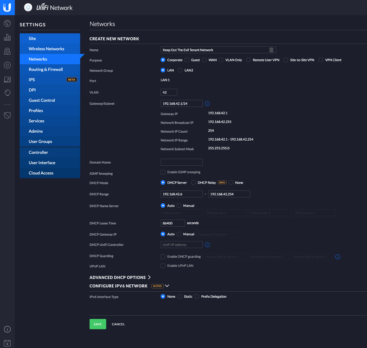
Click on Save and your network will be created.
That’s the network definition taken care of, now we need to make sure that clients actually connect to it. There are two main ways of doing that, one is creating a new Wireless Network that is connected to the right VLAN and Network. The other is to tie the VLAN to a given port on the Unify Switch, to ensure that everything connected to that particular port gets the correct network assigned to it.
1.3 Creating a new Wireless Network for your Isolated Network#
Creating a new Wireless Network is pretty straight forward. Just head to Settings->Wireless Networks and hit the +Create New Wireless Network button. Give it a Name/SSID, enable the encryption you want and set a Security Key. Next, expand the Advanced Options section, and select Use VLAN. Put in the VLAN ID you defined for your network in 1.1. You can leave the other settings as default.
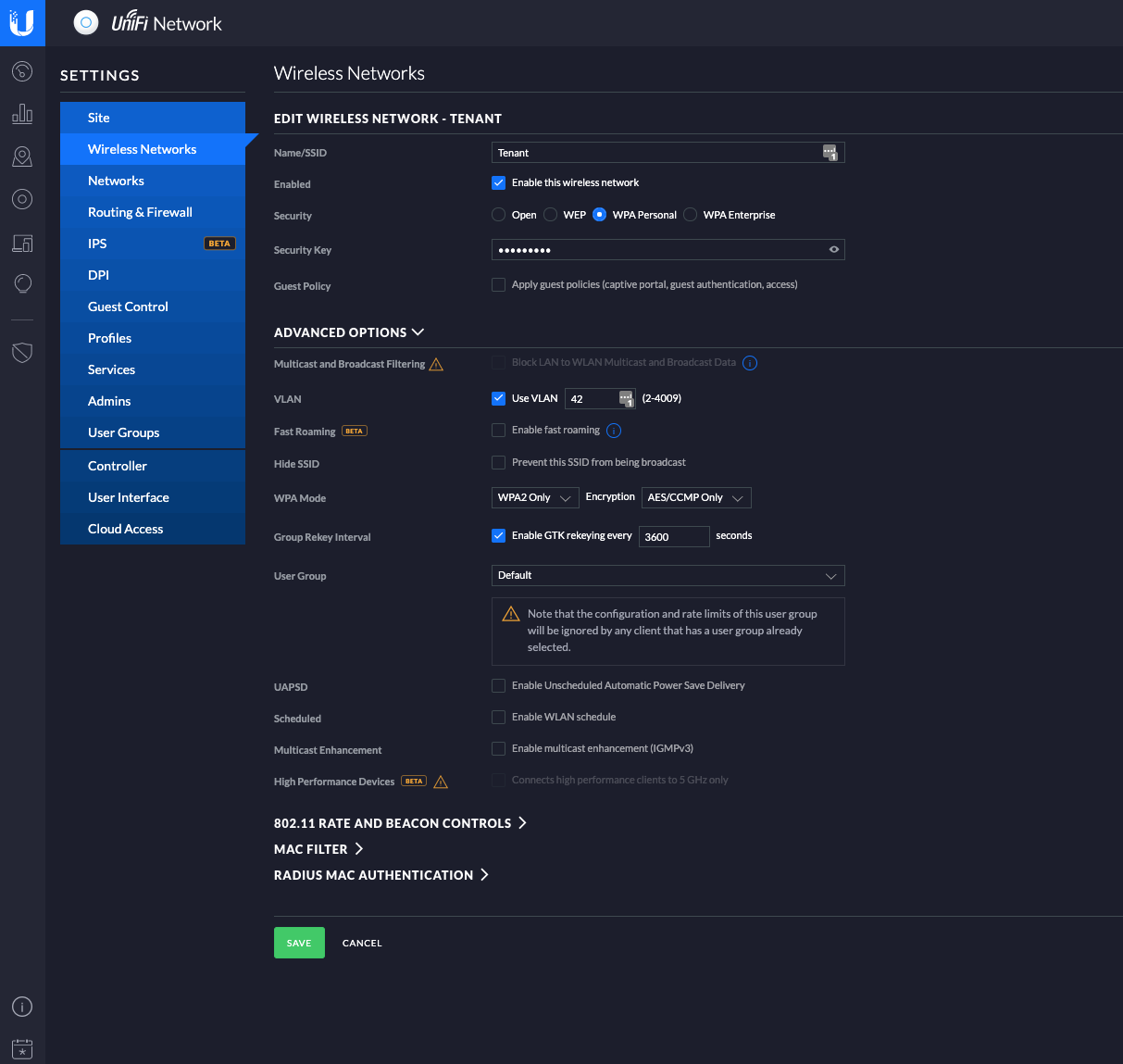
Once a device connects to your new SSID, it will automatically be put into the specified VLAN and receive an IP address from the virtual DHCP server running on that network. You can quickly test this by connecting your phone or tablet to this network, and see if you can reach the internet.
1.4 Assigning a VLAN to a Port on the UniFi Switch#
If you need to put a wired device into an isolated network, you can do that by defining the VLAN on the port it is connected to on the UniFi Switch. I have done this, in addition to creating the Isolated Wireless Network in order to prevent my tenant from just removing my AP, and plugging in something else, and then getting direct access to my internal network (Note to self: I should really move away from the using the default VLAN for my main local network)
In order to do that, go to Devices and find your Unifi Switch. Click on it, and find the Ports icon. Find the correct port, and click on the dropdown for Switch Port Profile. The dropdown will show you all the available networks, and you can then choose which one to assign to that particular port on the switch.
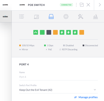
Select your network, and click on Apply. Now, anything that connects to that port on the switch, automatically gets the VLAN ID and assigned IPs you specified for the network. Det default setting of ALL means that the VLAN needs to be tagged on the device itself, and that is not something I want in this scenario.
1.5 Blocking traffic from your new VLAN/Network to your other networks#
By default, UniFi allows traffic to flow between networks unless you block it. Since the purpose of this is to isolate the new network from existing ones, we need to pop some new firewall rules into place. Go to Settings->Routing & Firewall and find the Firewall tab. There you’ll get a list of different options, what we are looking for is LAN IN. Select that, and then click on +Create New Rule.
Give the rule a name, again this can be anything you want. All the other default settings are OK in this instance, since we’re looking to block traffic. Make sure that Before predefined rules is selected, the same with Enabled.
Expand Source and change the Source Type to Network. Once that is done, use the dropdown menu to find the network you want to isolate and select it. Under Destination, change the Destination Type to Network and in the dropdown, select the network you don’t want device in your source network to access. In my case that’s the home.local network.
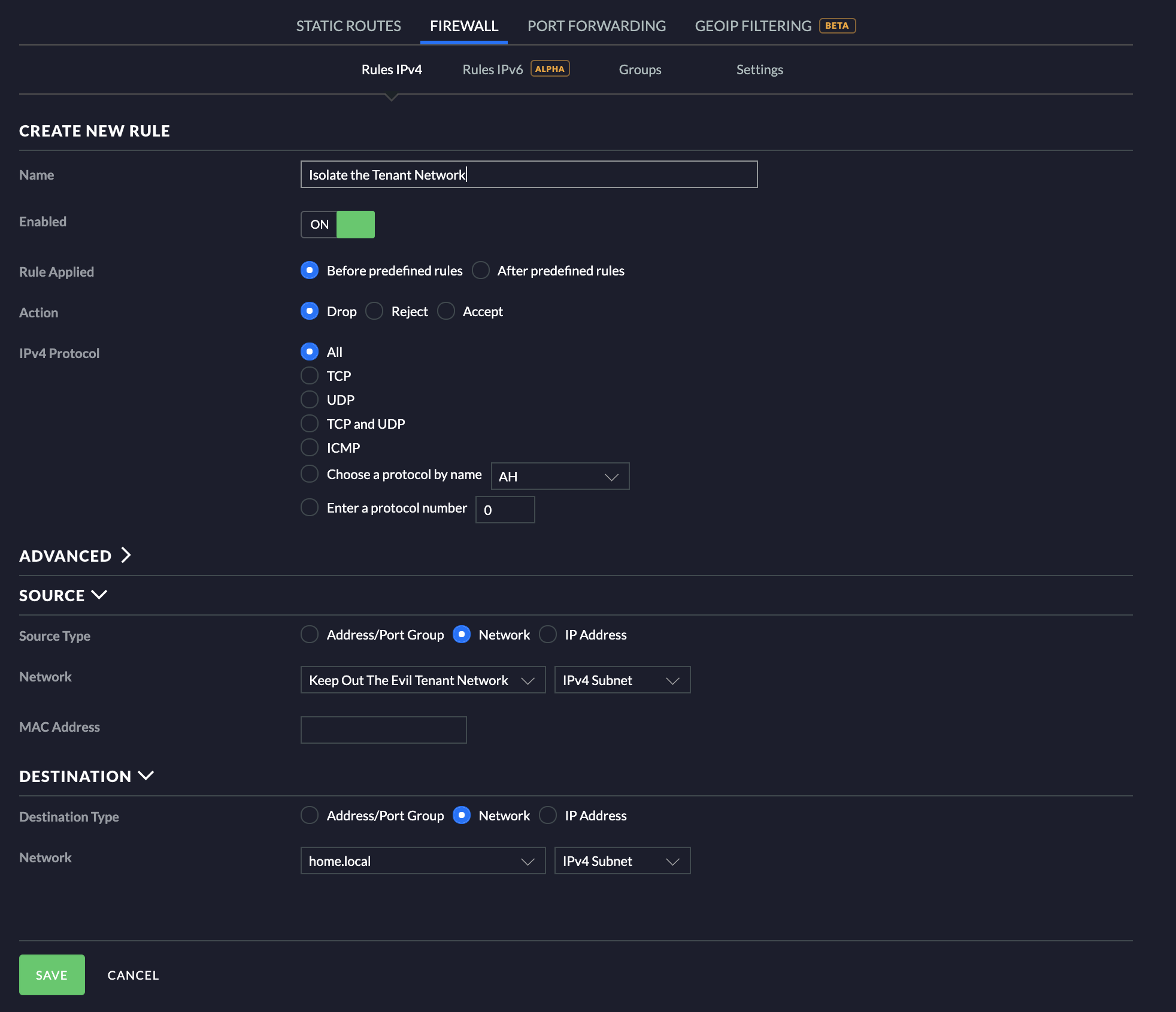
Click on save, and there you go! The rule should now show up under your LAN IN rules. The way it’s set up now, all traffic from all other networks to the new network is allowed, but no traffic is allowed to be initiated from this new network to the network selected in destination above.
Once again, connect a phone ot tablet to the new network and use a ping app for your chosen platform to verify that the network is indeed isolated from your other networks.
Note: Do not ping any of your other UniFi gateways for this test, since you will be able to ping all gateways that are defined (they are all virtual, really). Try to ping, or otherwise access, something else, or you might think the isolation isn’t working as it should.
Repeat this process if you have several networks you want to isolate.
Conclusion#
So, once this is done, traffic is blocked between the new isolated network (VLAN 42) and your other networks (if you created rules for all of them) — but they still have internet access. The networks now are isolated from each other unless you specifically open up communications between them.
Creating isolated networks provides a lot more flexibility than using Guest Networks (which also have their place), while still protecting your internal networks.